![]()
![]()
![]()
romod series
.
.
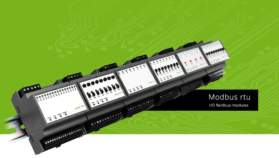
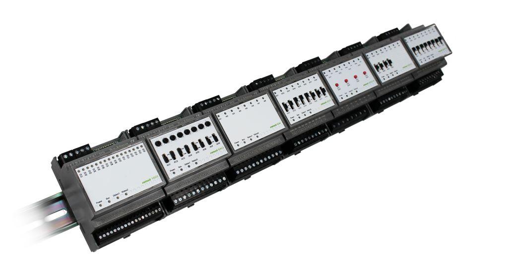
The Romod module family is a set of romutec® local override/indication devices (LO/ID) for mounting on DIN rails. It consists of various types of I/O modules. The connection to the MODBus master device is done via a RS485 connection. The communication takes place via MODBus RTU.
Each module has its own RS485 bus interface, therefore no gateway module is required. The address is set by means of an 8-pin dip switch. The available range of addresses is 0 ... 255.
The local override/indication devices operate as slave modules with any MODBus master. The baud rate of the protocol will be automatically detected when receiving several telegrams.

romod 8DO-R- 8DO-R Railmodul
8x LED DO-status, 8x A-0-H, 24V/2A

Front
The digital output module romod 8 DO-R is a Local Override/Indication Device (LO/ID) which is used to control eight 1-stage motors, or other digital actuators. By means of the integrated switches, it provides the ability of manual override of the DOs which are usually controlled via Modbus commands. The relay outputs provide the normally open contact of each relay. They will be contacted via terminals. The signal that will be switched by the relay contacts also has to be connected via terminals. The eight relay outputs are divided into two groups of four outputs. The two groups are not linked internally, so both COM terminals must be wired. Important: The signals to be switched must have the same phasing. For each DO there is a LED present which signalizes the status of the digital outputs. Using the settings in the relevant Modbus register, for each of this LEDs the color can be defined to either red, green or orange. Furthermore, the LEDs can be controlled via Modbus commands, provided that this option previously has been defined in a configuration register. This setting can be made individually for each LED. The current positions of the switches can be read out using two registers. Doing so, one register shows the switch position 'Manually ON' and the other one the switch position 'Automatic'. There is a register that displays whether and which switch has been operated since the last time this register has been read. When reading this register, all bits are reset to zero. If the position of a switch has been altered several times, e.g. from AUTO to OFF and back to AUTO, a change will be displayed, anyway. All digital outputs can be configured so that they will assume a defined state ('safe state') if the module has not received valid bus telegrams via the Modbus for a certain time. These predefined states are set separately for each output, whereas the time until activating the safe state is common for all outputs of a module. Note: The time for triggering the 'safe state' should not be too short in order to avoid malfunctions as they can occur, e.g., when another device which is connected to the bus fails and will so cause time-outs. Regarding the system configuration (addressing, maximum number of modules connected to a Modbus Master interface, installation, connection to the bus etc.), please follow the instructions in the chapter Configuration.
|
Datasheets |