![]()
![]()
![]()
romod series
.
.
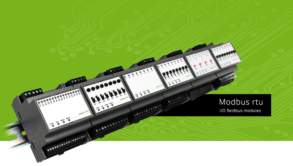
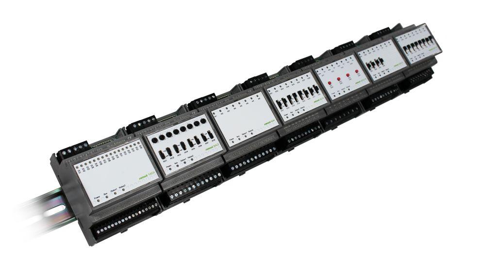
The Romod module family is a set of romutec® local override/indication devices (LO/ID) for mounting on DIN rails. It consists of various types of I/O modules. The connection to the MODBus master device is done via a RS485 connection. The communication takes place via MODBus RTU.
Each module has its own RS485 bus interface, therefore no gateway module is required. The address is set by means of an 8-pin dip switch. The available range of addresses is 0 ... 255.
The local override/indication devices operate as slave modules with any MODBus master. The baud rate of the protocol will be automatically detected when receiving several telegrams.

romod 16DI- 16 DI Railmodul
16x LEDs DI-status, 16 connector-DIs

Front
The digital input module Romod 16DI is used for signaling of up to 16 digital messages. These include operating messages, error messages such as frost, filter dirty or fan belt damaged, and status messages such as damper positions. The control of the inputs will be done with 24 V DC switched by external dry contacts that are connected to the module via terminals.
Article Group: 0310Article Number: 00002929The digital input module romod 16 DI is used for signaling of up to 16 digital messages. These include operating messages, error messages such as frost, filter dirty or fan belt damaged, and status messages such as damper positions. The control of the inputs will be done with 24 V switched by external dry contacts that are connected to the module via terminals. The reference potential is defined via the COM terminals and can be both, 0 volts and 24 volts. When using a reference potential of 24 volts, a control of the digital inputs with 0 V potential can be realized. The two COM terminals are connected internally, but not with the GND of the power supply, i.e. that reference potential for the inputs has to be connected anyway. Using the settings in Modbus registers, you can select open circuit or closed-circuit principle for each input separately. Also the color of each of the 16 LEDs is adjustable via a Modbus configuration register, either red, green or orange. Furthermore, the LEDs can be controlled via Modbus commands, provided that this option previously has been defined in a configuration register. This setting can be made individually for each LED. The digital inputs can be used as counters. For each input, a prescaler may be adjusted in order to count, e.g., just every second or third pulse. A subsequent change of the prescaler also results in a (retroactive) amendment of the corresponding counter values. The pulse duration must be at least 10 ms to be reliably detected. The maximum counter value using a prescaler of 1 is 4,294,967,296. There is a register that displays whether and which DI has changed since the last time this register has been read. When reading this register, all bits are reset to zero automatically. If a DI's status has altered several times, e.g. from 0 to 1 and back to 0, a change will be signalized, anyway. Regarding the system configuration (addressing, maximum number of modules connected to a Modbus Master interface, installation, connection to the bus etc.), please follow the instructions in the chapter Configuration.
|
Datasheets |