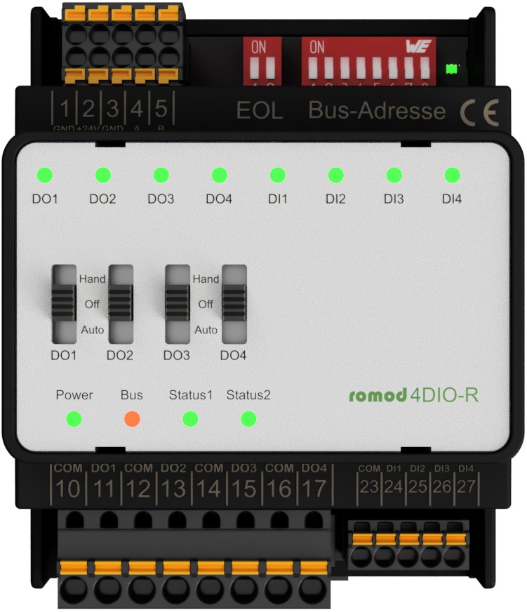
romod 4DIO-R- 4DIO-R Railmodul
4x LED DO-status, 4x LED var, 4x A-0-H, 24V/3A
The module romod 4 DIO-R provides four digital inputs and four digital outputs. It is used to control four 1-stage motors, or other digital actuators, and for signaling of up to four digital messages. These include operating messages, error messages such as frost, filter dirty or fan belt damaged, and status messages. Furthermore, the romod 4 DIO-R is a Local Override/Indication Device (LO/ID), i.e. by means of the integrated switches, the module provides the ability of manual override of the DOs which are usually controlled via Modbus commands. Digital outputs: The relay outputs provide the normally open contact of each relay. They will be contacted via terminals. Important: The signals to be switched must have the same phasing. By means of configuration registers there can be defined that the digital outputs will also follow the signals of the digital inputs (in addition to the control via Modbus). Both, static control and toggling are possible. Moreover, on and off delays can be set for each output, as well as minimum times for the states ON and OFF. Please note: The configured switching delays and minimum on / off times will only work when the outputs are activated via bus commands. Whenever manual override is applied, the operator will be responsible for the adherence to these times. Mutual interlocking of outputs is also possible. For each DO there is a LED present which signalizes the status of the digital outputs. Using the settings in the relevant Modbus register, for each of this LEDs the color can be defined to either red, green or orange. Furthermore, the LEDs can be controlled via Modbus commands, provided that this option previously has been defined in a configuration register. This setting can be made individually for each LED. The current positions of the switches can be read out using two registers. Doing so, one register shows the switch position 'Manually ON' and the other one the switch position 'Automatic'. There is a register that displays whether and which switch has been operated since the last time this register has been read. When reading this register, all bits are reset to zero. If the position of a switch has been altered several times, e.g. from AUTO to OFF and back to AUTO, a change will be displayed, anyway. All digital outputs can be configured so that they will assume a defined state ('safe state') if the module has not received valid bus telegrams via the Modbus for a certain time. These predefined states are set separately for each output, whereas the time until activating the safe state is common for all outputs of a module. Note: The time for triggering the 'safe state' should not be too short in order to avoid malfunctions as they can occur, e.g., when another device which is connected to the bus fails and will so cause time-outs. Digital inputs: The control of the digital inputs will be done with 24 V switched by external dry contacts that are connected to the module via terminals. The reference potential is defined via the COM terminals and can be both, 0 volts and 24 volts, i.e. that reference potential for the inputs has to be connected anyway. When using a reference potential of 24 volts, a control of the digital inputs with 0 V potential can be realized. Using the settings in Modbus registers, you can select open circuit or closed-circuit principle for each input separately. Also the color of each of the 16 LEDs is adjustable via a Modbus configuration register, either red, green or orange. Furthermore, the LEDs can be controlled via Modbus commands, provided that this option previously has been defined in a configuration register. This setting can be made individually for each LED. The digital inputs can be used as counters, but only for DC signals. For each input, a prescaler may be adjusted in order to count, e.g., just every second or third pulse. A subsequent change of the prescaler also results in a (retroactive) amendment of the corresponding counter values. The pulse duration must be at least 10 ms to be reliably detected. For AC control of the inputs, the edge detection has to be delayed via configuration registers (see registers R1101 and R1111). In case of 50 Hz, this value should be set to at least 40 ms in order to avoid the counting of false detections. There is a register that displays whether and which DI has changed since the last time this register has been read. When reading this register, all bits are reset to zero automatically. If a DI's status has altered several times, e.g. from 0 to 1 and back to 0, a change will be signalized, anyway. Regarding the system configuration (addressing, maximum number of modules connected to a Modbus Master interface, installation, connection to the bus etc.), please follow the instructions in the chapter Configuration.
|
Datasheets |


