![]()
![]()
![]()
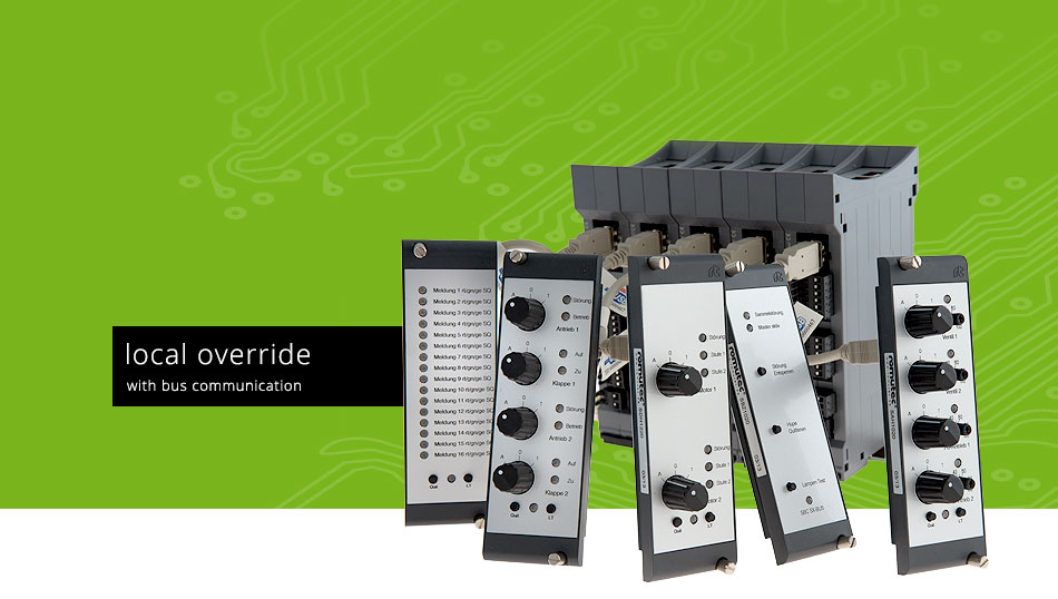

MLM1030- 16xLED red/yellow/green, 19" module 3U/8HP + rail-module

Front

Back
USB-RS485, MLM1010 rail-module + MLM1020 19"-module, USB-cable
Article Group: 0201Article Number: 00002906The digital input module MLM1030 (consisting of one MLM1010 and MLM1020) is used for signaling of up to 16 status messages. These include operational feedback messages, fault messages such as frost, filter polluted or fan belt broken as well as status messages such as flap position open/closed. The control of the LEDs will be done with 24 V DC switched by external dry contacts that are connected to the module via removable terminals. The reference potential is defined via the COM terminals in groups and can be both, 0 volts and +24 volts (DC). Using the settings in MODBus registers, you can select open circuit or closed-circuit principle for each input separately. Also the color of each of the 16 LEDs is adjustable via a MODBus configuration register, either red, green or orange. For the digital inputs there are two registers available which provide three pieces of information for every DI. Namely, these are the current state of each DI, and whether a message has accrued newly (new incident) or already was been acknowledged, provided the message is configured as a fault message. The selected LED color is not relevant for this function. If the memory for fault messages of a digital input is activated, in the mentioned registers the bit 'new incident' is set when a new fault message accrues (every digital input has its assigned bits in the register). When the fault message is acknowledged (via push button at the module or via MODBus command), in addition to the bit new incident, the corresponding bit fault acknowledged will be set, provided the fault is still present. If the fault message is no longer active, the bits are just reset to zero. However, if the fault disappeared before acknowledged, the bit new incident will still remain set until the fault message has been acknowledged. Four summarised signals are formed from the fault messages that are connected to the inputs 1-4, 5-8, 9-12 and 13-16. The summarised signals are available via terminals as so-called 'conditional outputs' (ground referenced, +24 V). This applies to the setting 'conditional outputs autonomously', otherwise these outputs have to be controlled directly via MODBus commands. All status messages will be transferred via MODBus to the MODBus master device (DDC/PLC) where they are available for further processing. However, the LEDs of the front module can also be configured so that they are controlled via MODBus commands. The digital inputs (terminals) can be used anyway, but in this case without signaling at the front module. Regarding the system configuration (addressing, maximum number of modules connected to a MODBus Master interface, installation, connection to the bus etc.), please follow the instructions in the chapter Configuration.
|
Datasheets |